Harma
A project to assist over-caffeinated electrical engineers in soldering.
Pensel
Pensel, or brush/pencil in Swedish, is the device the user interfaces with to control the robotic arms. It is this sub-component that I will first tackle to make the whole system. The design as it stands is as follows:
There will be one unified design to control the iron, solder, and/or wire/components. As such, there must be a generic control methodology built into the Pensel. The Pensel will have as follows:
- A three position toggle switch for the user to indicate what mode the Pensel is operating in (Soldering iron, solder, or wire/component).
- One push button to indicate that we are actively moving and want the robot to respond
- Another push button to do the action supported by the mode. For example:
- Feed solder
- Feed wire
- release component
Hardware Basics
- STM32F302K8U6
- ARM® Cortex®-M4 (with FPU)
- I²C, UART/USART, USB, DMA, PWM, WDT
- 72MHz
- Orientation / motion sensor for orientation and movement detection
- LSM303DLHC accelerometer and magnetometer for version 1
- LSM9DS1 accelerometer, magnetometer and gyroscope for version 2
Pensel v1
Sensors
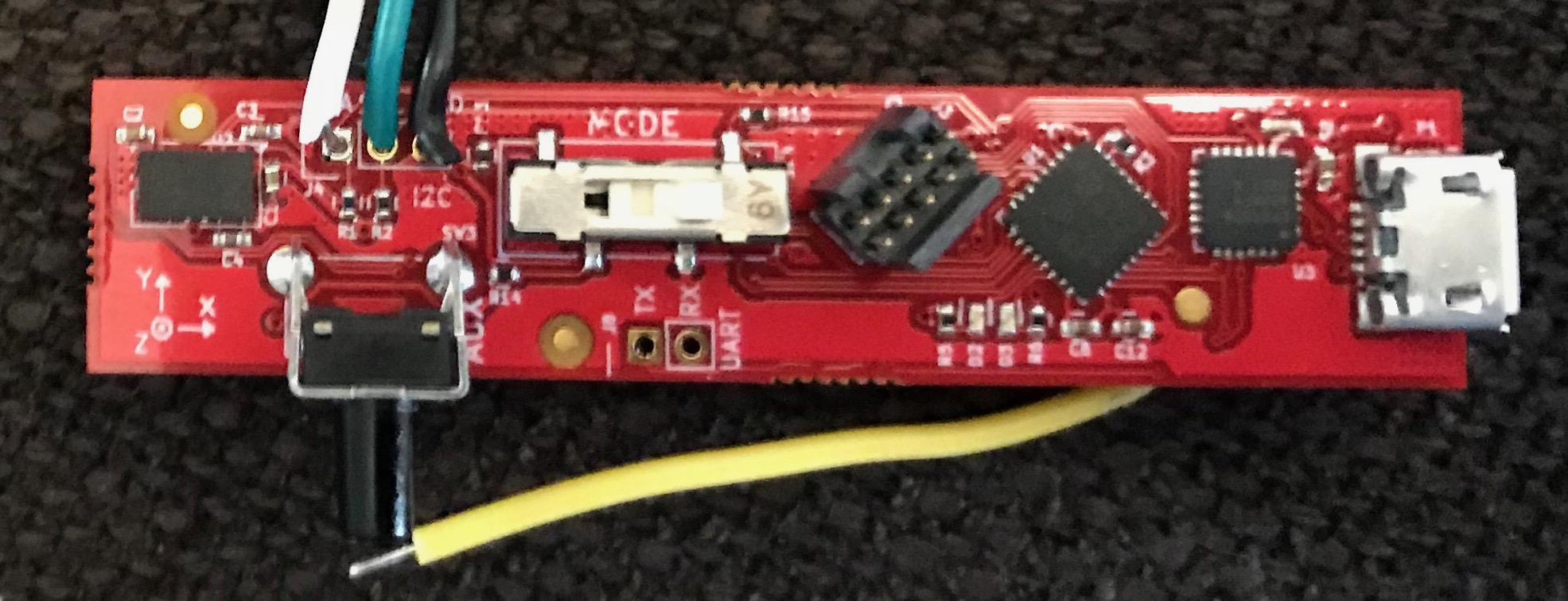
Pensel v1 utilized the now obsolete LSM303DLHC, an accelerometer/magnetometer orientation sensor. I was hoping to achieve absolute orientation sensing with the gravity vector and magnetic north vector. This is, however, very difficult with magnetometer data, as it is very noisy and susceptible to local perturbations.

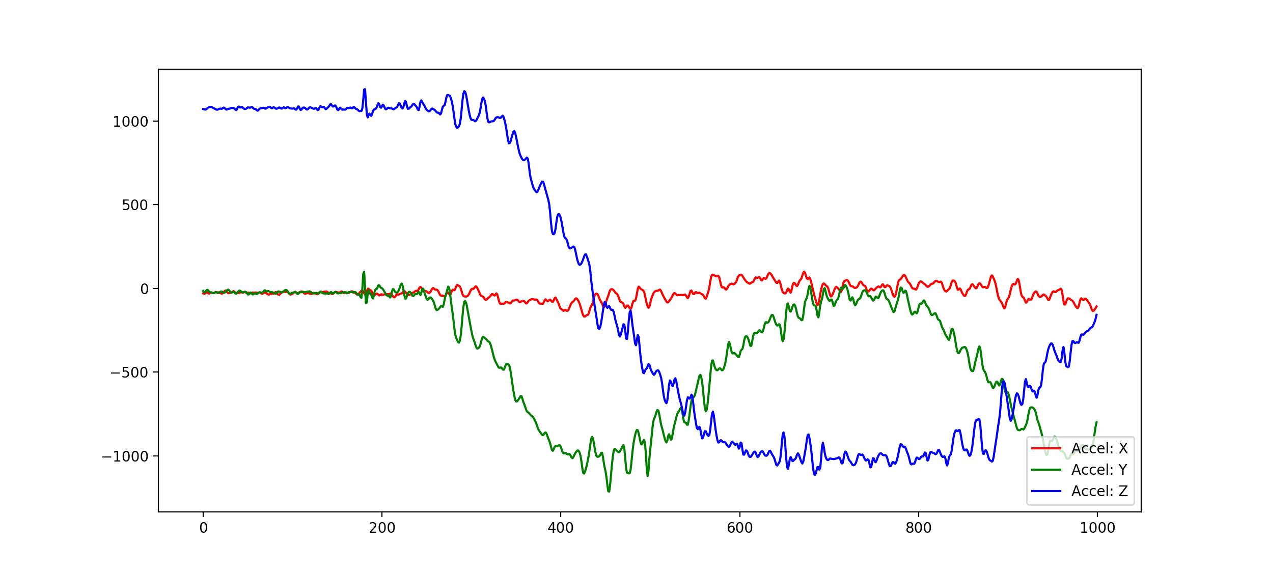
The accelerometer data, however, looked very promising.
Communication
The communication method was also less than ideal in v1. I utilized a USB to serial converter chip to provide easy communication to the host, however to accommodate the high data-rate sensors and have a general purpose report get/set architecture, I basically re-implemented a USB HID device over serial, which doesn’t make much sense.

Pensel v2
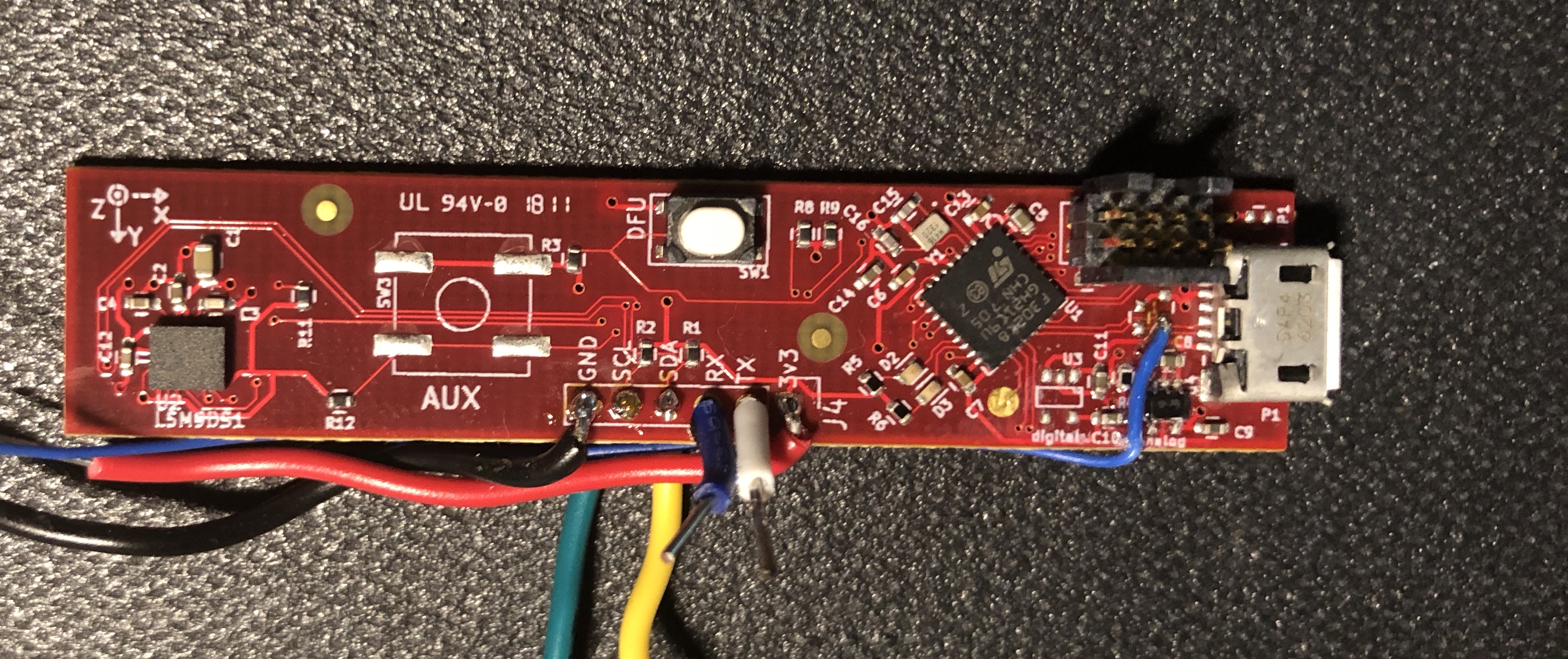
Pensel v2 aims to rectify the issues with v1 by using a more robust, in production accelerometer, magnetometer, and gyroscope sensor, the LSM9DS1. It also will eliminate the USB to serial converter in favor of a direct USB connection and a custom HID USB device. It is also my first adventure into four layer boards, which made routing a dream.
Current Progress
I am currently working on getting the USB stack up and working. I found that I forgot the 1.5k pull-up resistor on the D+ pin of the USB connection, which is required to indicate device speed and device attachment. I have attached a bodge wire to the D+ net (luckily I had pads for filter capacitors in case they were needed) and am working on soldering some 0805 resistors to that line.
Initial Software Design
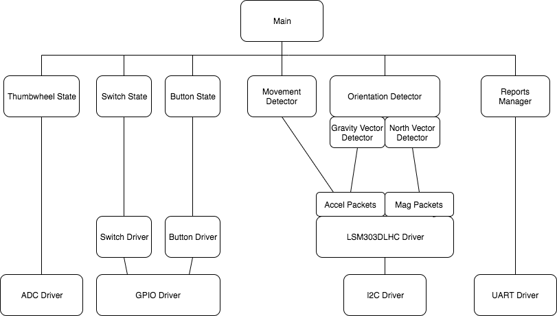
Below is an overview of all of the modules in the system. This is only an initial cut at the system and is subject to change.
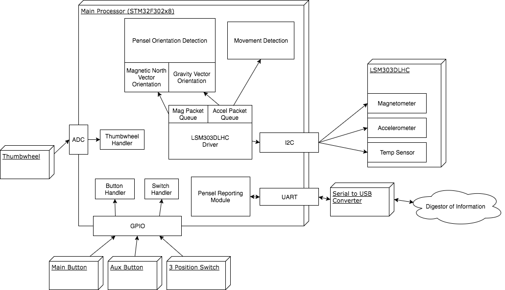
Below is an overview of the control and call structure of the system.
