Holmes Engineering
Projects by Tyler Holmes
Current Projects
Harma
The Harma (meaning Mimic in Swedish) project is a solution to my shaky, over-caffeinated hands. It is a robot-assisted soldering tool, like robot-assisted surgery, but much less expensive (hopefully).
The idea is to have two distinct sub-systems working together: one or two Pensels, to detect orientation and movement of the users hands, accompanying one or two robotic arms (cool Swedish name to be determined). The arms mimic the user’s input as well as performing special actions on a button press, such as feeding solder or wire.
More info about the project can be found here.
Pensel
The Pensel project (meaning brush or pencil in Swedish) is the sub-component of the Harma project that gets the user’s input. The user holds the Pensel like it was the soldering iron and the robotic arm mimics their movements on a finer scale, as well as filtering out jitter.
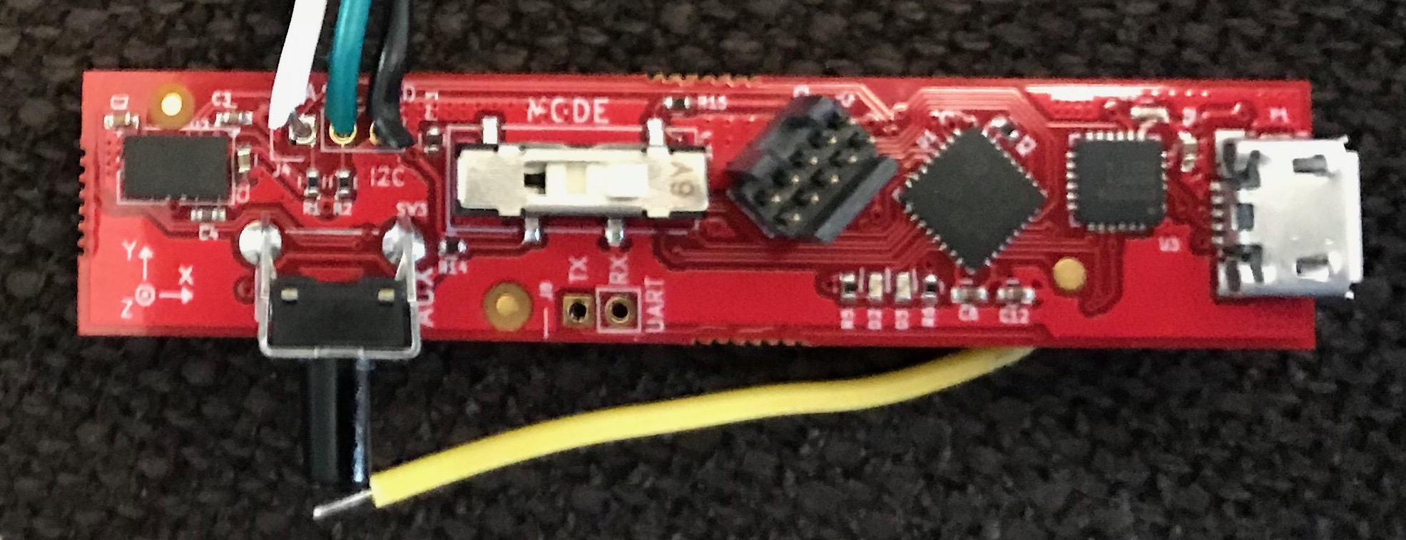
The above is my first cut at the PCB. I was able to bring up all sensors and got accelerometer and magnetometer data out of the orientation IC. Unfortunately, the board fried after working on it for a while. I am planning on continuing the project with some Adafruit breakout boards in Rust. More info can be found here.
Past Projects
Battery Powered Oven Temp Monitor - in Rust!
This is the new and improved variant on my original oven temperature monitor, but rewritten in embedded rust and much more battery efficient. Doing this project made me want to never write embedded C ever again.

Battery Powered Oven Temp Monitor
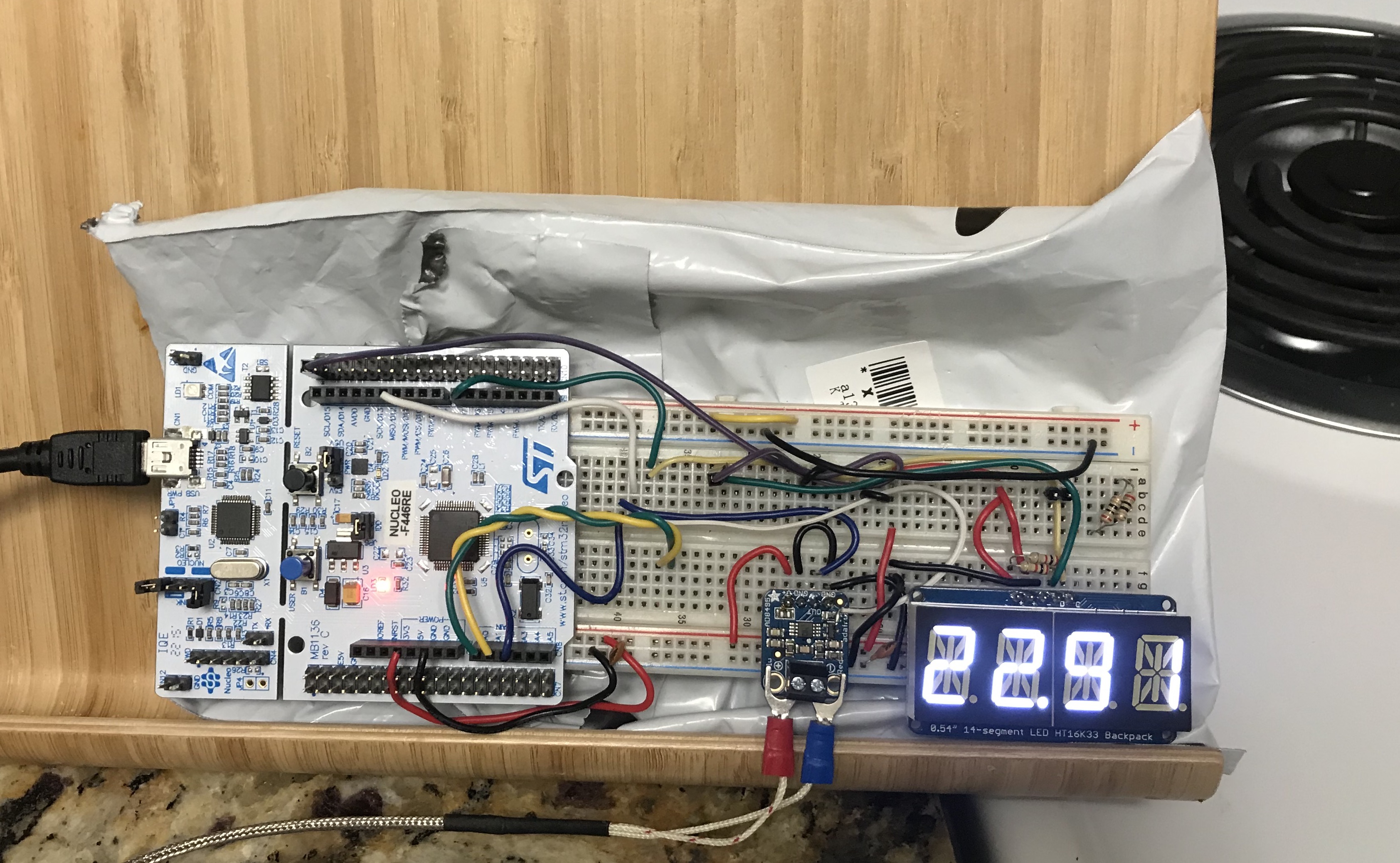
This project began when my wife and I moved to a new apartment in early 2017 that didn’t have an oven that displayed the temperature. That’s a super easy problem: get a thermocouple, some sort of display, and an Arduino and you’re done! However, I didn’t want to deal with plugging this thing in, so to make it tidier and more interesting, it is battery powered. This gave me the opportunity to work on a power limited device, which I have not done before.
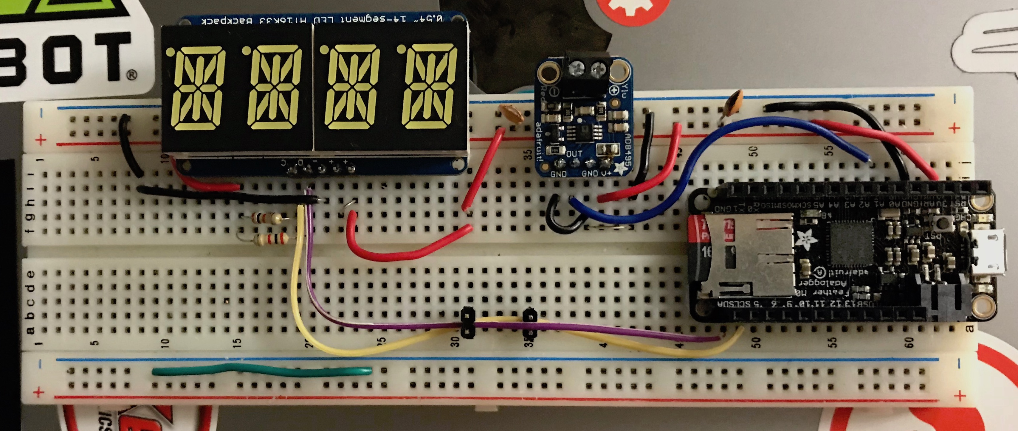
I first prototyped this project with an Arduino and components from Adafruit to get a baseline of performance. This baseline then could be improved on with sleeping the system, turning off the thermocouple amplifier when not using it, and so on.
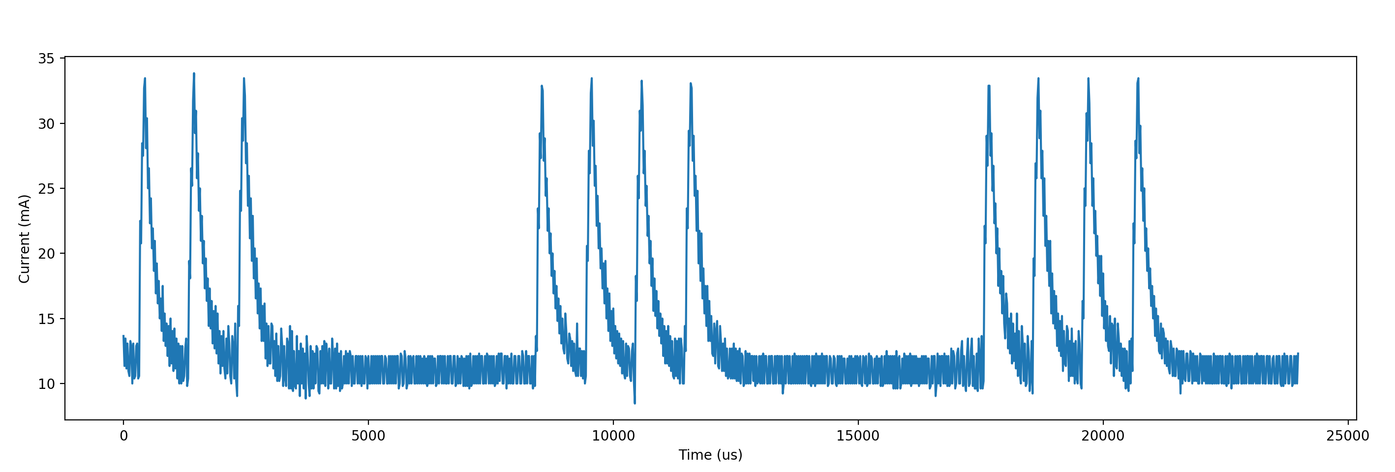
After this initial cut, I then moved to using an STM Nucleo F446 dev board I had laying around to do the final design. This allows me a bit more control over power settings as well as having less power hungry components on the board. Unused demo peripherals such as the accelerometer were disconnected. I initially used a breadboard setup to make sure it all worked. I then soldered it up to be put in a permanent enclosure
Binary Clock
The Binary Clock project began because I wanted a simple clock that displayed the time in binary coded decimal. After looking online and not finding any that I liked, I made my own.
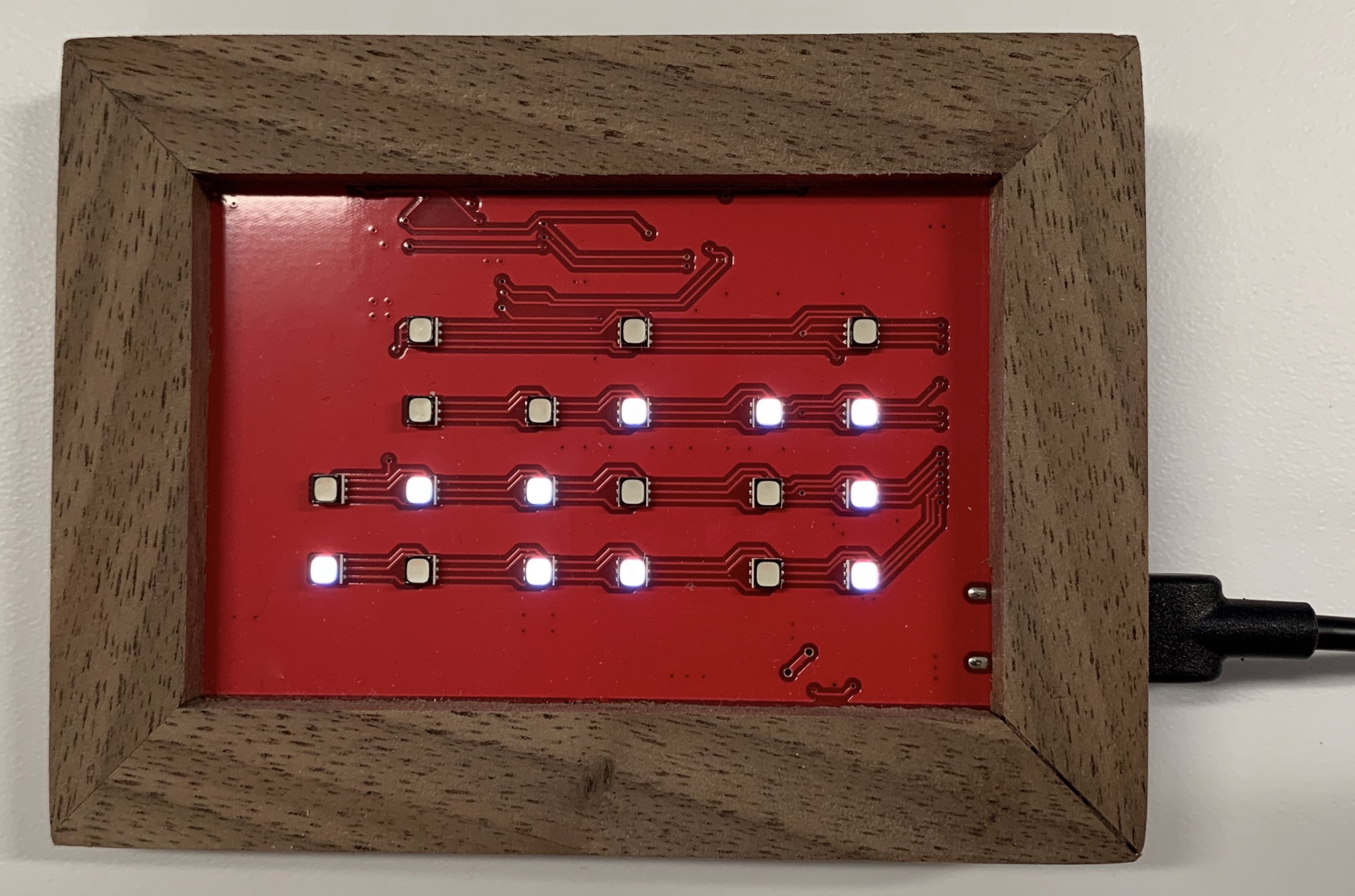
More information, documentation, and a high level overview can be found here.
Ladder 42
Ladder 42 (AKA candleBot) was a project for my Microprocessors II lab that I worked on with Broderick Carlin. The project is based on the Trinity College Firefighting Robot Competition. The goal of the competition is to have the robot find the fire (a candle) and extinguish it as fast as possible.
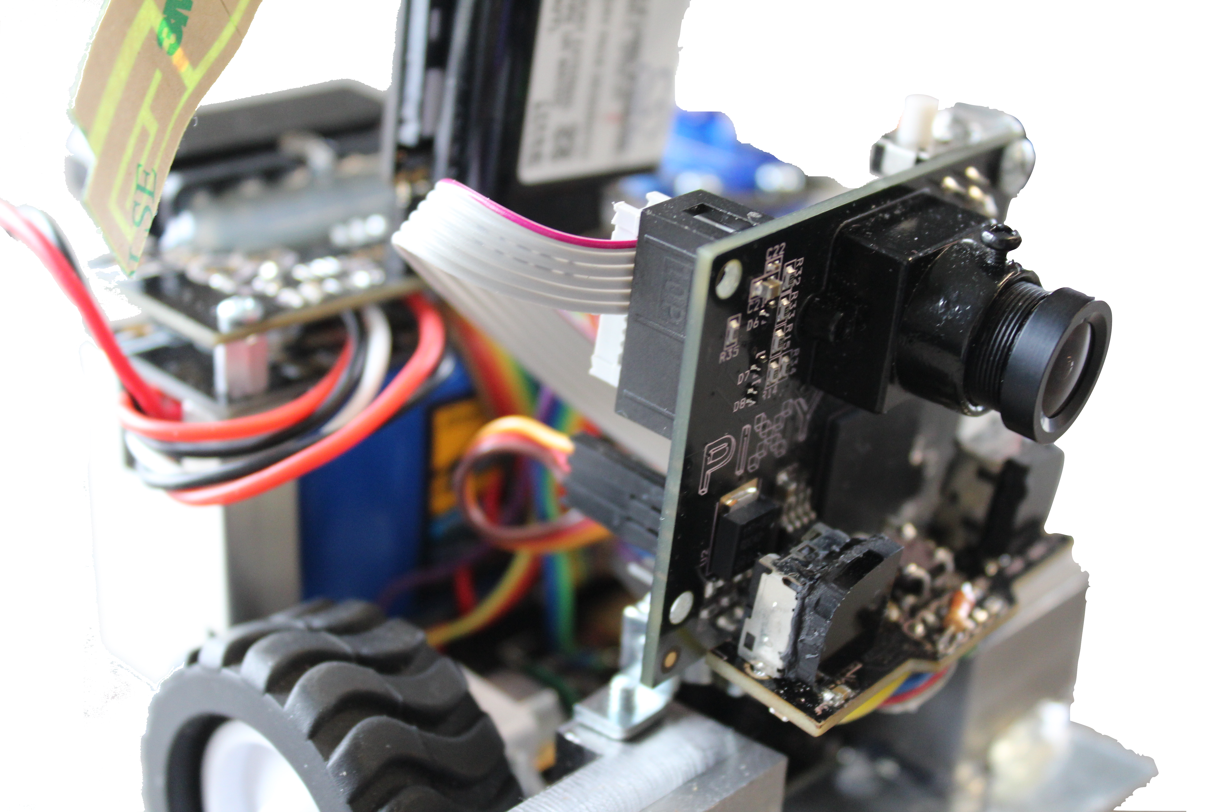
We went about this by getting a Pixy to do image processing, two old Wii-motes to sense IR, two compass MEMS ICs, a color sensor to go on the bottom to detect the white circle that is under the candle, and a cell module to text the “fire department” to put out the candle. A bit overboard, but we wanted to go all out on this project. We designed all of the PCBs ourselves and got them fabricated by Dirty PCB.
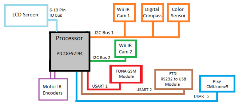
The compasses were dead on arrival because we selected too small of packages and did the reflow ourselves. The Wii-motes were very easy to interface with (there are many guides online to do this) so detecting the candle’s position was easy. However, the image processing we needed (edge detection) was not supported out of the box by the pixy. One of my main parts of the project was to try to get edge detection working on the pixy camera.
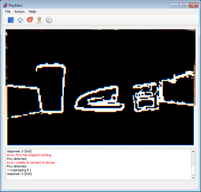
Stark corners were easy, but getting rid of spurious noise and repairing torn edges was very difficult. The Pixy also had a fish eye lens on it, distorting straight lines. Edge detection was working for the most part, but I failed to get a communication scheme with the main MCU finalized before the competition. This project was for a semester long course, so we just ran out of time. I also was responsible for the code interfacing with the color sensor, the I2C driver, and part of the wiimote code.
Senior Design
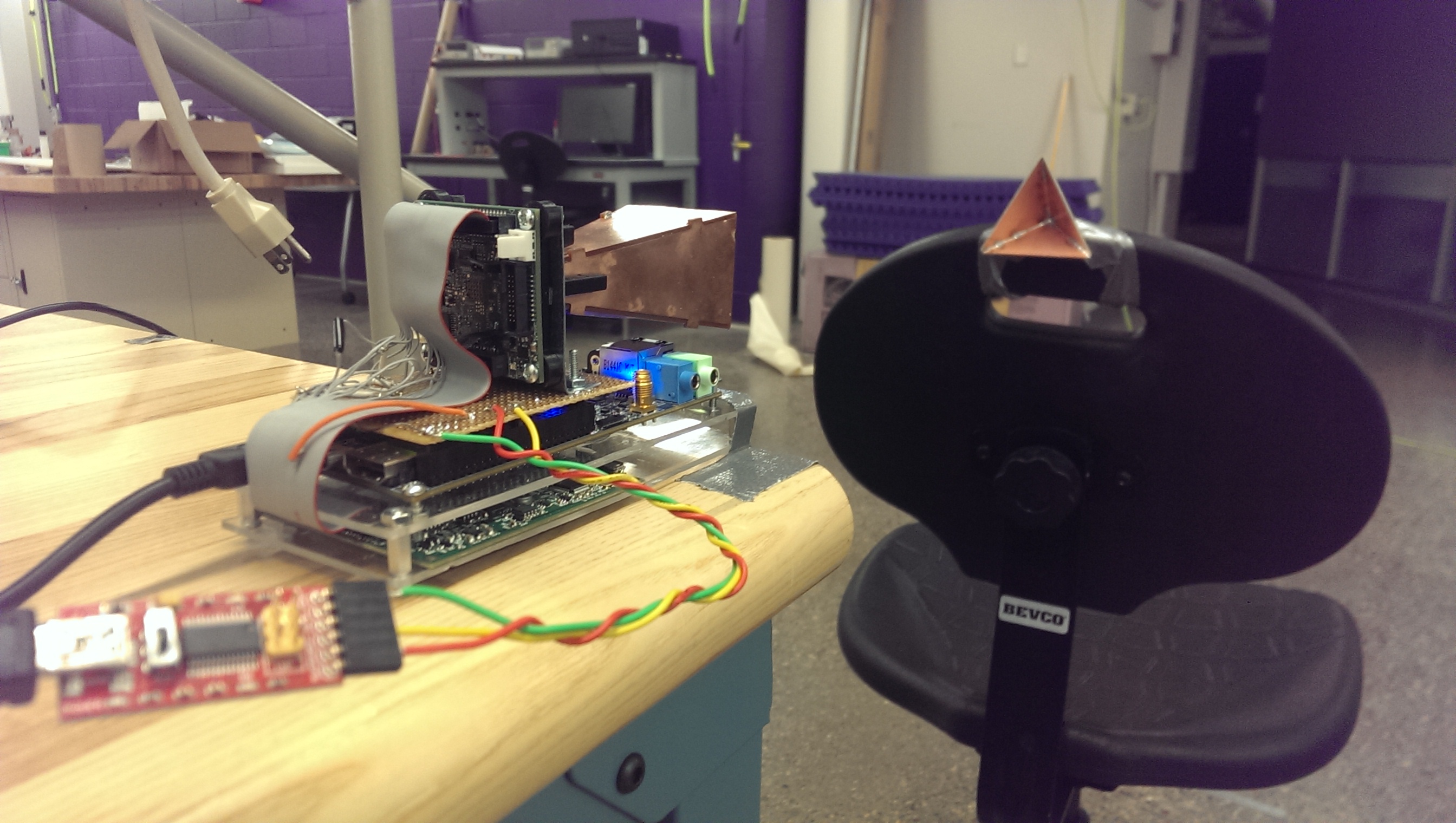
My Senior Design project was an EHF 60 GHz radar sensor for detecting distance. The basic idea is that the radio chip, a custom ASIC, outputs a continuous ramp in frequency from 60 to 67 GHz over a few milliseconds, hits the target object, and comes back. By the time the radar wave returns, it is slightly slower in frequency than what is currently being outputted. The ASIC then subtracts these two signals in the frequency domain and outputs the result, now in the kHz range, to be used by the application processor.
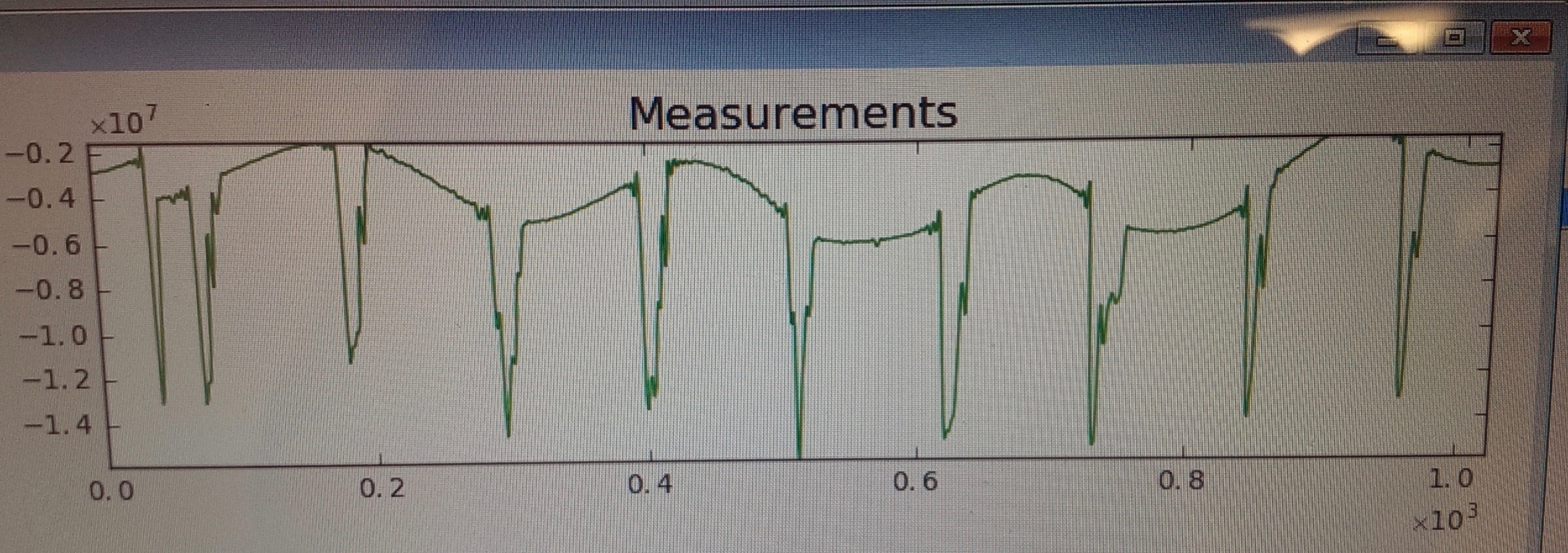
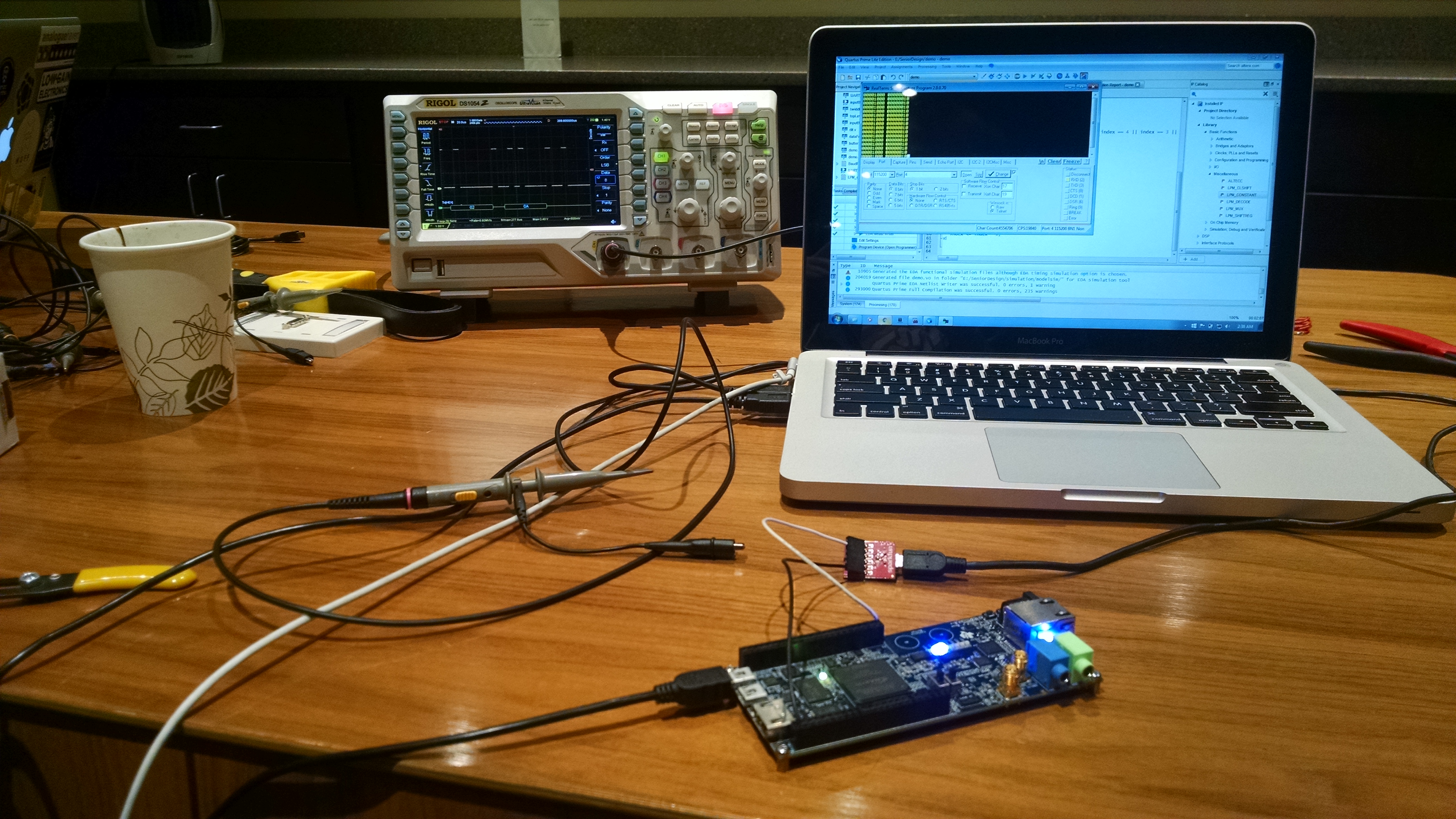
We used an Altera FPGA to do the DSP. I was responsible for the DSP (written in Verilog) to detect the distance of objects, which was proportional to the output signal from the radar ASIC. I also wrote a UART driver. We were mostly successful in detecting the object. The fundamental frequency seen in the above plot is correlated to the distance of the object, but the large regular spikes were due to an error somewhere in the signal path that we could not identify.
Ice Dancer
The Ice Dancer was a project in collaboration with Dr. Thomas Shepard and Dr. Thomas Rodengen to measure ice thickness formation during the winter on Minnesota lakes.
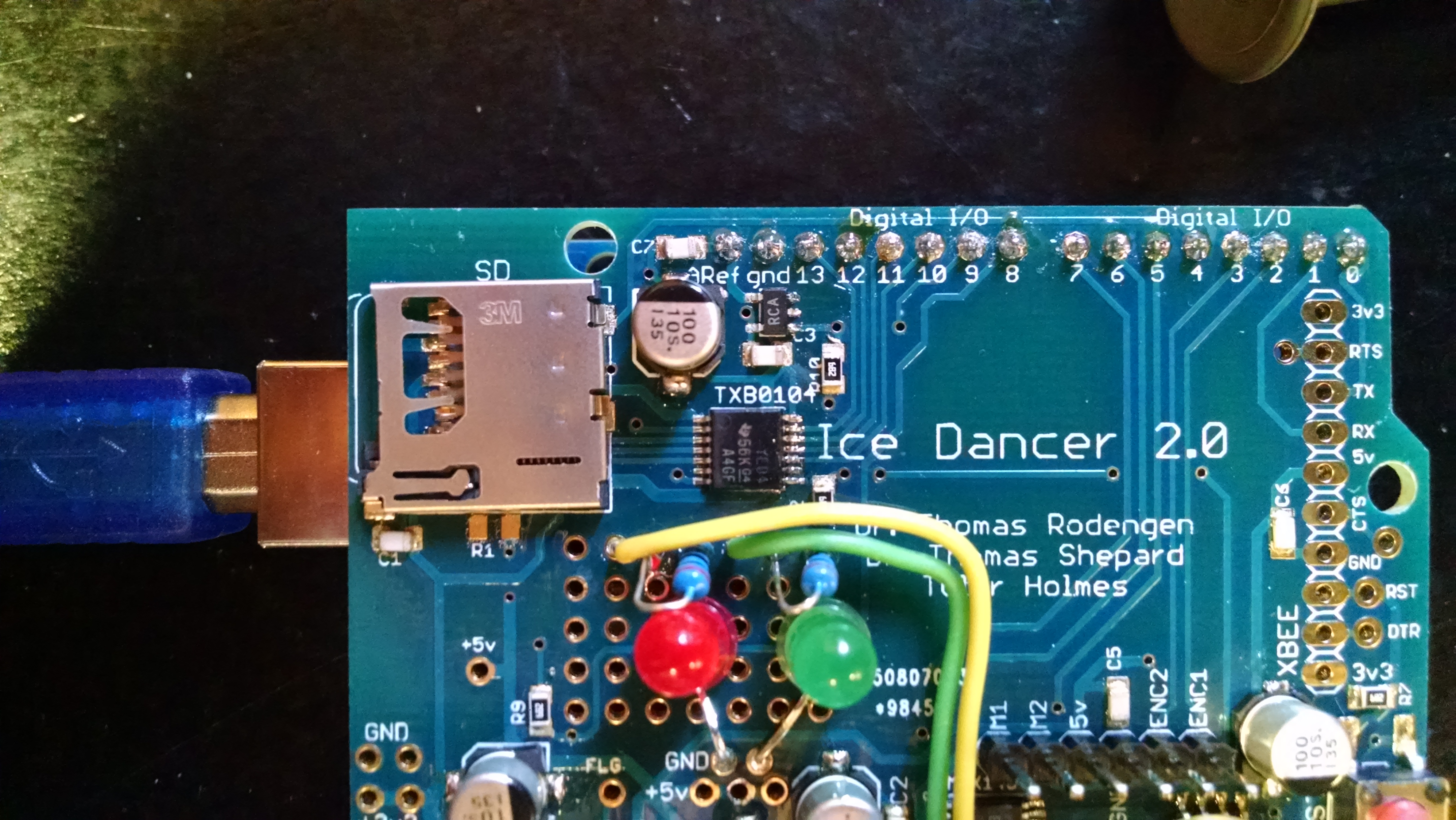
The Ice Dancer works by freezing a PVC pipe into the ice with a stopper on the bottom and a metal ring around the outside. The Ice Dancer then lowers a magnet down to the bottom on a string which magnetically attaches to the metal ring and pulls it up. The Ice Dancer measures the distance the magnet travels via an encoder on the motor (which then can be used to infer the ice depth). The Ice Dancer determines if it is pulling the metal ring up by measuring the amount of current the motor is drawing.
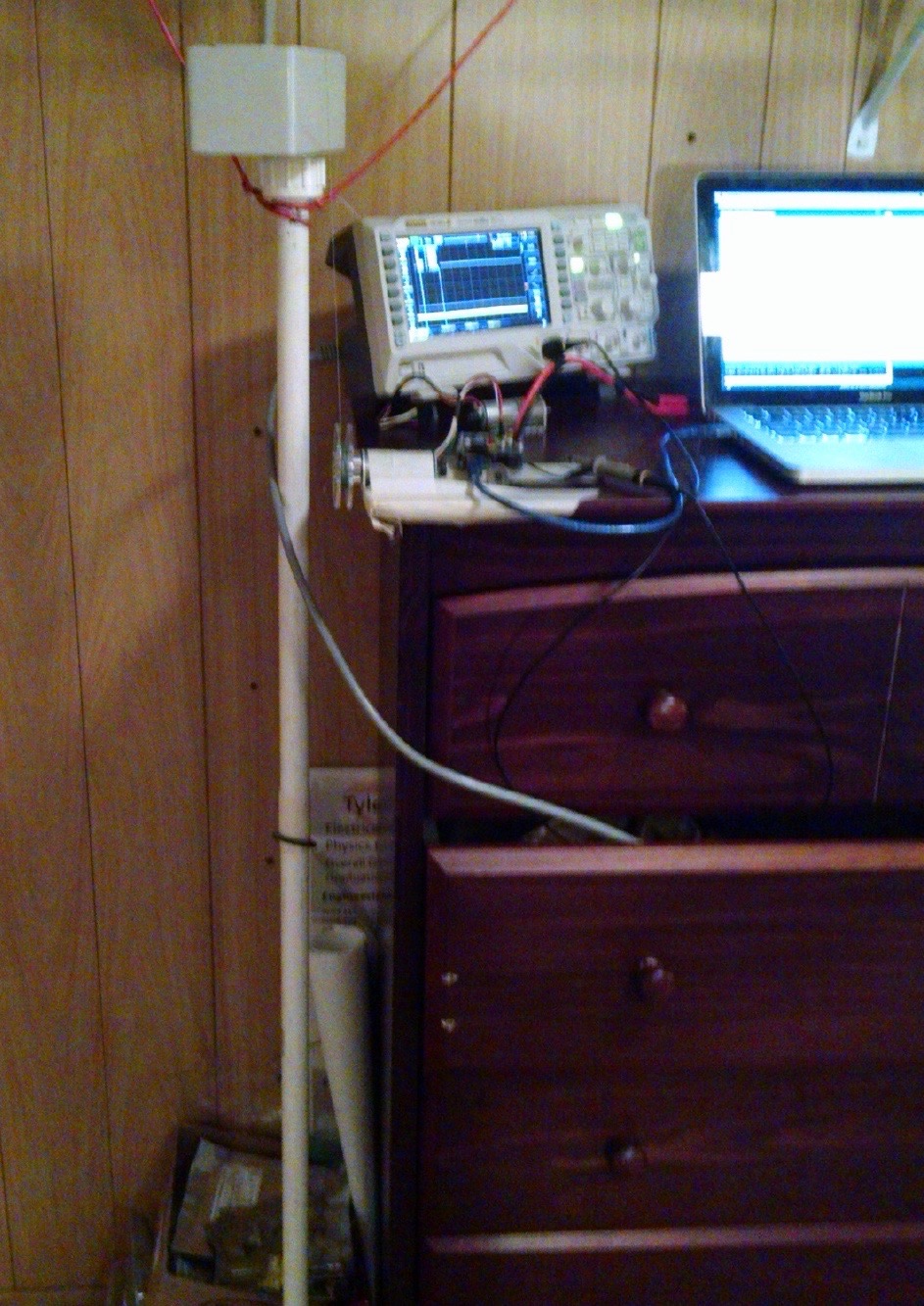
Everything for this project worked, except for the SD card reader. I unfortunately had to end the project there without resolving this as Senior Design was taking up too much of my time.
PiBot
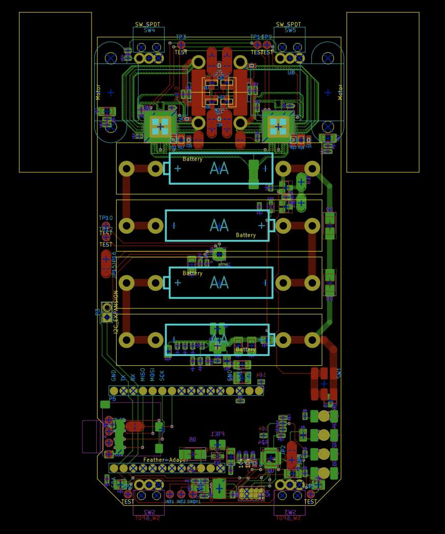
The PiBot project is a collaboration between myself and Broderick Carlin. The goal of the PiBot project is to provide the maker community with an easy to use, but powerful robot platform. It does this by off-loading the motor driver logic as well as the distance and velocity calculation to our co-processor, allowing the user’s processor to handle more important tasks.
This project uses the NXP MKL03Z32VFK4, a M0+ processor. I’m writing the firmware while Broderick is responsible for the board design. The initial firmware is complete, but the board design is still in progress. More information as well as the firmware, unit tests, and board files for this project can be found here on the GitHub page.
